
|

|

|

|
SONAR LE Documentation is based on the full version of SONAR. Some screenshots, folder paths, features and other references may differ from your installation.

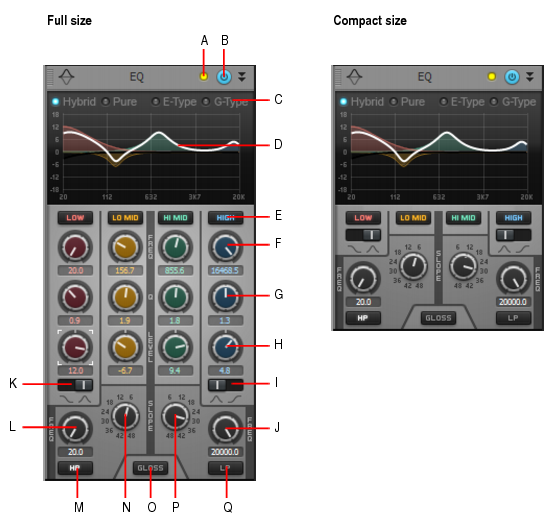
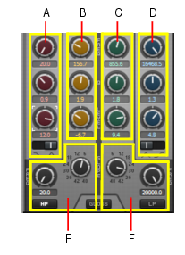
, Low-Mid
, Mid-High
and High
bands. Enabling a band allows it to be processed with equalization. The knobs and graph curves are color-coded per band:
. Enables the Low Pass filter, which attenuates high frequencies above the Low Pass frequency while allowing other frequencies to pass unfiltered.
. Enables the High Pass filter, which attenuates low frequencies below the High Pass frequency while allowing other frequencies to pass unfiltered.
. Adds a smooth breath and presence to the high end without any harshness using a unique gloss filter.
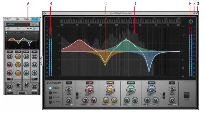
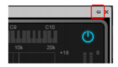
Figure 321. QuadCurve EQ fly-out panel.A. Click to open fly-out panel B. Input meter C. EQ plot D. FFT spectrum analyzer E. Output meter F. Pin fly-out panel G. Close fly-out panelDo one of the following:
in the top right corner of the fly-out panel.
Tip - Searching Documentation
Tip: To search for a specific topic, type your search query in the Search Cakewalk.com field at the top right of this page.
When the search results appear, click which product's documentation you would like to search to filter the search results further.
Note - Using Offline Help
Note: If you prefer to always use offline Help, go to Edit > Preferences > File > Advanced in your Cakewalk software and select Always Use Offline Help.
If you are not connected to the internet, your Cakewalk software will default to showing offline help until an internet connection becomes available.